
Harold Hall
Metalworking
Workshop Projects
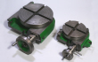
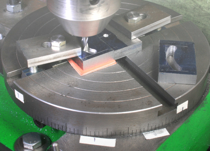
Having positioned the rotary table on centre, place the locating fence on it and lower the centre into this, Photograph 24, and clamp it in position. This ensuring that the centre mark on the fence is concentric with the rotary table. Now add the workpiece to the rotary table with it up against fence and the right hand end aligned with the end of the fence, and clamp in position. However, to avoid the cutter breaking through and damaging the rotary table place a piece of thick card, between the workpiece and the table. Do also set the down feed stop to avoid an accident by a momentary loss of concentration.
Remove the locking from the milling machine's X axis and traverse the table back
through a distance of 24.5mm, setting the radius required as a result. Lock the table
in the X axis once more. With a 5mm slot drill in the machine rotate the table until
it aligns with one of the machine-
Table (62)
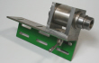
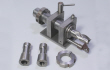
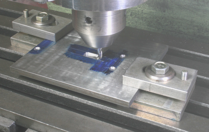
This is a simple part but have included Photograph 26 which shows my set up for milling the rectangular cutout required. Note how the packing that allows the cutter to break through to complete the cutout is inherent in the clamping method. I also used my X and Y table stops to fix the cutout size making the process a very easy one as it did for the Top Plate which has a similar cutout. Next set up the table in a tilting vice and machine the angle on the underside of the cutout, Photograph 27, the purpose of which is to permit the table to be set at an angle whilst still keeping the opening in the top surface as small as is possible, useful when dealing with small workpieces.


The Lathe Mounting assembly starts on the next page.

24
25

26
27