
Harold Hall
Metalworking
Workshop Projects
Variable Stroke Mechanism Assembly
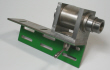
Whilst the Input Drive Spindle was the only assembly to have major turning operations, this is the only one to have much milling beyond just machining the ends of bar and flat plate. The assembly being shown in Photograph 19.
Bearing Carrier (52)
Cut a 35mm length of 20 x 8mm steel and mark out the position of the holes, also
a machine-
Accurately set up a fence on an angle plate at 60 degrees, including in the fence a 5.5mm diameter hole for holding the carrier. Mount the Bearing Carrier onto the fence, ensuring that one edge is firmly against the angle plate and the hole F at the top. Mount the angle plate onto the milling machine table.
Variable Stroke Mechanism.
(Take an M6 screw and create a slight taper on the end and screw this fully into hole E and dropping the 6mm diameter ball into the hole. Unscrew the screw slightly so that the ball falls well back into the hole and start machining the angled edge, lowering the cut until it is down to the mark made to define the position of the 14mm edge, Photograph 20
Now, wind in the screw fully and note the ball is being raised above the machined surface. This needs to be sufficient to ensure that it will eventually clamp the carrier in its chosen position, I would suggest 0.5mm above the surface, if less, the ball can be lowered and a little more machined off as the 14mm dimension is not critical, then test once more.
Remove the carrier rotate and again fit to the fence ensuring that the part is against the angle plate and machine the second end to produce a flat 26mm wide. Do not be concerned regarding the 12/14mm dimensions as the position of hole D is not crucial.
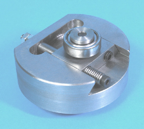


19
20





Suggestions for an alternative Fixed Stroke Mechanism