

Harold Hall


Metalworking
Workshop Data
Whilst it is much less likely to be needed than in the case of resistors, I will for completeness cover the situation of capacitors in series and parallel, mathematically they are the reverse of that with resistors. The effective capacitance of two capacitors in parallel is therefore the sum total of the two.
Ct = C1 + C2
In the case of two, or more, in series the result is less than the smallest.
1
Ct = —————————————
1 1
——— + ———
C1 C2
Inductance
The subject of inductance is much more complex than that of resistance, or even capacitance, and can only be covered here in the most basic terms, there are though some surprising similarities with capacitance.
Whilst components having near pure resistance or capacitance do exist, typically a heater or a capacitor, pure inductance does not. An inductance will consist of a coil of wire that will have a resistance value and has to be taken into account in more complex applications, for these explanations though it will be ignored.
I am a great believer in the approach that it is easier to understand the what, if you have at least a basic understanding of the why. First therefor, I will give a very brief explanation of how electricity is generated magnetically.
Electricity generation
If a wire is connected to a sensitive voltmeter and laid alongside a magnet the meter will read zero. If then the magnet is removed it will be found that a voltage is developed as the magnet is moved and will again when the magnet is replaced but will vanish when the magnet is at rest. Similarly, if the wire is taken from the magnetic field a voltage will be apparent as it will be as it is being returned. From this it can be seen that a voltage is only produced when the magnetic field strength is changing, either increasing or decreasing.
Also of importance, is the fact that the value of the developed voltage is dependent on the rate of change rather than the value of the field strength. For example, fast movement in a weak field can produce a higher voltage than a slow movement in a strong field. Another important fact is that the polarity of the generated voltage depends on whether the field strength is increasing or decreasing.
The change in field strength can be as the result of the wire or the magnetic field physically moving as in a generator or, the current in a coil changing resulting in a change of field strength which then generates a voltage back into the coil itself or another wound along side, as in a transformer. If it is a self induced voltage this is called "Back EMF" being an abbreviation of “back electromotive force”, "Counter EMF" is also used though rarely in the UK.
To recap on the important points. Value of the developed voltage is dependent on the rate of change of field strength, also, polarity is dependent on whether the field strength is increasing or decreasing.
Back to inductance
Let us now consider inductance.
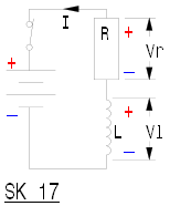
Sk 17 shows a voltage Vin being applied to an inductance L via a resistor R. At the moment of switch on the magnetic field, whilst weak, will increase rapidly and will cause a high voltage to be generated in the inductors own windings, back emf as explained above. The polarity is such that it opposes the supply voltage limiting the current flow as a result. However, as the field strength strengthens the rate of change reduces and therefor the back emf voltage being developed. The current increases as a result until its value is solely dependent on the applied voltage and the value of resistor R. At this point Vl will equal zero (on the basis that the coil has zero resistance).