
Harold Hall
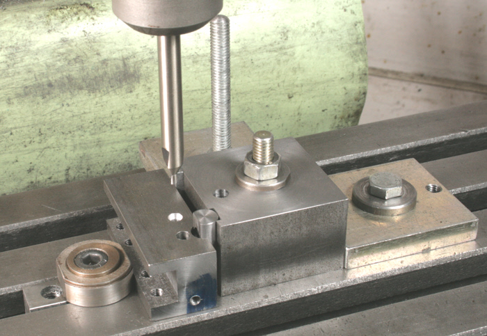
Photo 20 shows my method from which it can be seen that I also added a fence/support to the right of the Body. This making it doubly sure that the Body will not move as a result of the clamping pressure produced by the low profile clamp. Whilst unlikely, as the clamping pressure needs only to be light, being just a drilling operation, but such an event would probably make the subsequent holders scrap. The precaution is therefore advisable.
With the first Tool Holder now in place, locate the left hand side of the Body, then moving the locator to the left for hole E in the holder. Do take note of backlash and the 3mm gap between the body and the holder. Now centre drill and drill hole E 10mm diameter and 22mm deep. Repeat for the remaining holders.
There now remains the 7mm slot into the hole just drilled. Add a fence to the mill table and a centre in the machines spindle. Lower the centre into the 10mm hole (E) in a holder and move the table to the left until the fence touches the end of the holder, clamp the table (temporarily) in this position.
I anticipate, maybe wrongly, that most workshops will be equipped with the more common end mill sizes, 6, 8, 10 and 12mm etc. In which case, like me, a 6mm cutter will have to be used, that is unless a 7mm cutter is purchased specially for the task. The following works well so do not see the need.
However, using a 6mm end mill will need the slot widening both ways from its present position, (central on the hole) so will need moving left and right by 0.5mm. Photo 21 shows the end stops being set to make this possible. In producing the slot the end mill will be moved to left stop and then fed in to the 15mm dimension, then moved to the right and fed out. I have Y axis stops so set one for the 15mm dimension, otherwise it, will be a case of working to a dial reading.
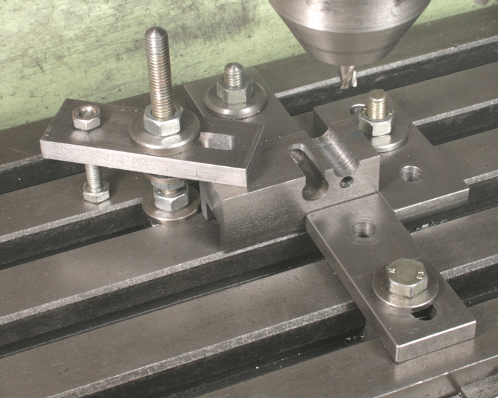
The final set up is seen in Photo 22 and shows that there is both a rear and right hand fences to set each holders position accurately and a single clamp for holding the part whilst machining. Whilst feeding the cutter down the slots left hand side its rotation will be attempting to force the holder back, this being prevented by the clamp and the rear fence. However, when moving outward down the right hand side the force will be attempting to pull the workpiece from under the clamp. Because of this a front support is required. This being moved out and replaced each time a new holder is placed for machining.
Close examination of Photograph 22 shows that I secured the clamp stud to the table so that it would not loose position between holders. Also, there is a nut below the clamp to preventing it from falling fully when the holder is removed. A suitable compression spring under the clamp would of course have been better, I must equip myself with some.
Metalworking
Workshop Projects


20
21

22