
Harold Hall
The Clamp Assembly (S1)
The next stage is to make the Clamp Assembly starting first with the Clamp Piece
(S1-
The remaining parts, rivet (S1-
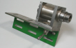
Finish the end of the Operating Piece by filing to match the curve of the Clamp Piece, also file the ends of the rivet. If though you have a collet chuck for your lathe you may like to turn the ends for a better finish. There is not much available length to hold but sufficient provided you take it easy. Photo 23 shows the process.
Next task is to drill the hole A in the Operating Piece, its position being important so as to ensure the holders are held securely. In one Tool Holder only, drill and tap M3 as shown in Sk. 6, fitting the clamp assembly and using an M3 screw to hold it in place. Do inspect the result to see that the clamp piece is in line with the hole and not tilted.
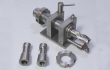
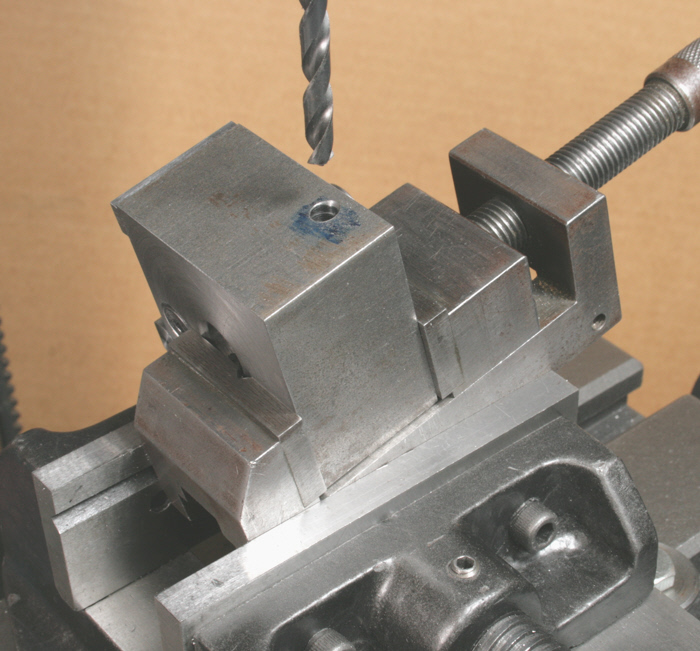
Fit the assembly onto the Body using two 2.5mm thick spacers to space them. For this, it will be necessary to have removed the Locating Key and Spacer from the Body. Place in the drilling vice and drill through the existing hole in the body to drill hole A in the Operating Piece, Photo 24.
At this stage, drill hole E in the body. I overlooked this requirement until I had all but finished the project and found that I could not hold the body in the vice as the locating key, spacer and clamp assembly were now fitted. The reader may be interested to see how I overcame this, without dismantling the parts, doing it by using what I term as a vice in vice set up, Photo 25.
The Locating Key and Spacer can now be finally fitted, the Spacer using double adhesive and the Key very firmly with two screws. In is essential that the Key clamps against the two corners of the groove, check by testing with a thin piece of material, say 0.1mm thick, that there is space between the Key and the base of the groove. If this is not the case, mill a small flat on the rear of the Key.
Once the project is complete and has been in use a few times it would be wise to check the tightness of the two screws just in case the corners of the groove have relaxed a little.
Metalworking
Workshop Projects



23
24

25