
Harold Hall
Workshop Processes


The Base
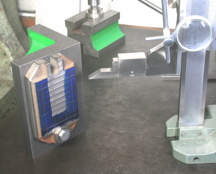
This, as seen from photograph 1, is a thin casting that has been cast, as one would expect, with the tapered faces being the shallow sides.
I chose to machine both of the large faces (essential) and the two long edges (optional)though as we shall see later it is very difficult to ensure that these are central and parallel to the vee in the block. However, as I intended to hold the part in the vice when machining the larger faces it was also essential that I machined the edges for the purpose. Photograph 9 shows that I held the part in the vice when machining the long edges, ensuring of course that the first edge was firmly against the bed of the vice when machining the second so as to ensure that the faces were parallel.
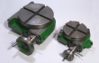
With the two longer edges now machined it was held in the machine vice and the first main surface machined, Photograph 10. Then, rather than again using the vice, I chose to mount the part directly on the machine table using some low profile clamps (see here), Photograph 11. The advantage of the method being that it was potentially more accurate as it would bypass any errors in the bed of the vice, and or errors in the parallels used. Much more important though, being eliminating the effect of jaw lift.
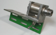
With the base machined this far I next marked out the position of the holes doing this with it fixed to the angle plate using one of the base's fixing lugs for the purpose and marked out the long axis positions first. Then, standing the angle plate on its end marked out the positions for the other axis ensuring by this method that the second axis was at right angles to the first, Photograph 12. The positions of the holes in the vee block were also marked out but this was much easier with it being a regular shape. With that done the holes were drilled, tapped and counterbored as required.
Unfortunately though, as the holes in the base were counterbored their size was governed
by the size of the pin on the counterbore in my case, 5.5mm for a M5 screw. As a
result there was a generous clearance for the screw and the vee block could therefore
return to the base in a different position each time it was removed and refitted.
I had early in the process considered machining the edges of the base again at this
stage to make them parallel with vee but now realised that this would be pointless.
Should the viewer wish to make this more of a precision item then dowelling the parts
to ensure perfect re-



9

10
11
12