
Harold Hall


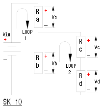
So far, no doubt, you have assumed that the voltage source is from a battery or other fixed voltage supply. Frequently though, an element of a circuit is just fed from some other portion of the overall circuit, Sk 10 shows an example.
Metalworking
Workshop Data
Here resistors b, c and d form loop 2 and again the sum total of voltages will be zero, that is Vb minus Vc minus Vd will equal zero. The same rule would also apply if we considered a third loop comprising Vin, Va, Vc and Vd.
When considering Sk 7, it was stated that the output voltage could be arrived at purely by taking the ratio of the resistors R1 and R2 in relation to the supply voltage. It will though in some cases be preferable to work the voltages out in terms of the individual resistance and the current flowing through it.
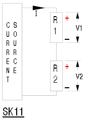
With this in mind, the law, known as "Ohm's law", detailing the relationship between volts, amps and ohms is equally applicable to an individual resistor in a complex circuit as it is to a single resistor connected direct to a supply (Sk3). Sketch 11 shows a circuit where the circuit is feed from a known current source rather than a known voltage the voltages V1 and V2 can be arrived at using the product of the current and the individual resistor values.
V1 = R1 x I and V2 = R2 x I
The above illustrates that Ohm's law can be used to calculate the value of the unknown, which ever of the three values this is, even for a single component in a complex circuit. The alternative forms of the formula being.
V V
I = ——— or V = I x R or R = ———
R I
Power
So far we have discussed electricity in terms of voltage (pressure) and current (flow) neither of which individually give any indication of the work being done. Back to our water tank illustration, we could have a large head of water with the tap almost closed or an almost empty tank with a wide open tap, both moving the same amount of water. This because the water would be under higher pressure in the first case compared to the second. Work being done is therefor given by the product of voltage and current in a circuit, the result being in Watts.
Power = V x I watts
This parameter will be applicable to different components in differing ways, most simply it will be the heat generated by a heater. In the case of a heater the wattage value is the crucial value, being chosen so as to provide the amount of heating required. However, in the circuits above, the resistors are there to provide control over voltages required in other parts of the circuit, the power that the resistor consumes is coincidental to the working of the circuit. It is though essential to calculate individually the wattage dissipated by each so as to ensure that the resistor is working within its limits. If not, then the resistor will overheat and fail, even burn a hole in the printed circuit board, known to happen even in professional circles.
Returning to Sk 11 the power dissipated by each resistance could be calculated using the formula for power in terms of volts and amps, as above. As however, V = R x I then the formula Power = V x I can also be expressed as
Power = (R x I) x I
that simplifies to
Power = R x I².
From this it can be seen that for resistors carrying the same current the wattage consumed is proportional to the resistor values. Typically if R1 is twice the value of R2 so will be the power consumed. R1 and R2 can therefor be of differing power ratings and therefor physical size.