
Harold Hall
Fitting the Locating Key onto the base.
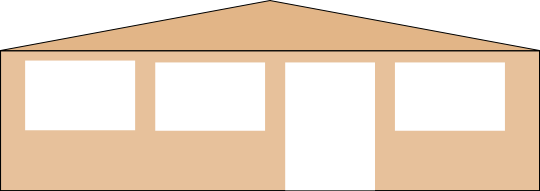
Most important when mating these two parts is that the key very firmly rests on the outer corners of the groove in the base so that the key cannot move when clamped into position using the fixing screws.
Out of interest
However, when I drew out the design I arbitrarily chose 10mm, 8mm and 2mm for the dimensions and found that this at normal size looked a perfect fit, touching both corners and sitting on the base of the groove. Doubting this, I did as I often do, that is to zoom into the desired area, this time to check the contact, or otherwise, of the key with the outer corners of the groove. My CAD program works to 7 decimal places and even at maximum zoom the fit appeared perfect, though drawing it out 20 times bigger a very minute error existed. This of course is academic as manufacturing tolerances would mean that such a fit could not be guaranteed.
Therefore, as it is essential that the key sits firmly between the two outer corners of the groove, there must be a slight clearance between the key and the base of the groove, 0.1mm will be more than enough. If this is not present then filing a slight flat on the key should make that available, more later.
Having made sure that the Locating Key will fit correctly, clamp it in place on the base, if possible using a toolmakers clamp as if suitably adjusted it will ensure that the flat surface is parallel with the side face of the base. This is not critical but a visual check will be more than adequate.
Now hold the Body in the drilling vice, placing it on parallels to accommodate the toolmakers clamp, Photo 17, and using the key as a guide, drill the base with the M3 tapping holes, followed by tapping M3.
The Locating Key can now be drilled and counterbored to take the M3 cap screws. The hole sizes will of course be dictated by the pin size on the counterbore . With that done, firmly fix the key to the base.
Metalworking
Workshop Projects


17