
Harold Hall
Workshop Processes


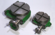
For a rotary table having a parallel bore, a plug could be made and centre drilled and the upper centre lowered into this, Photograph 13. The plugs main diameter and its centre drilled impression should be made without removing the part from the lathe to ensure concentricity. With that done the system is potentially more accurate than the method in photograph 12.
Having positioned the table relative to the machines spindle and placed the workpiece on the rotary table it remains to satisfy condition 3, that is to position the workpiece relative to the cutter for the machining to take place.
Returning to our simple example of radiusing the end of a link. With the cutter central above both the table and the link all that remains is to traverse the milling machine's table so as to produce the required radius. If the table is first traverse by the required radius the cutter will now be central over the radius line. All that is then required is to additionally traverse the table by half the cutter's diameter and one will be ready to produce the required radius. However, this may require you to remove more metal at one go than you will be happy with. In this case, make a note of the table's micrometer dial and move the table to reduce the initial cut. Progressive cuts can then be made working back to the micrometer dial reading just noted.
Mounting the workpiece
Basically, we have covered the essential principles of using a rotary table and all that remains is to consider the methods of securing the workpiece to the table. Whilst photographs 6, 7 and 9 have shown parts being secured using simple clamps, photographs 4 and 11 show a Keats angle plate being used. This illustrates that any work holding device within the rotary table's capacity can be considered as a means of holding the part being machined, typically a three jaw chuck, vice, angle plate or a collet holding attachment.
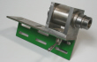
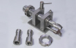
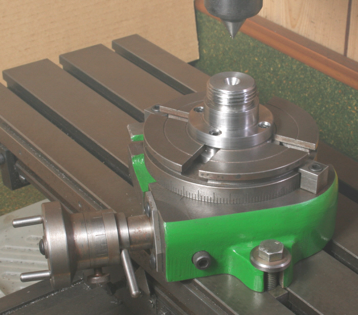
One possibility is to use a three jaw chuck. This can be the chuck normally used on the lathe and attached using an adapter that replicates the lathe's screwed nose, Photograph 14 showing an example. Note also how this adapter is centre drilled to aid positioning it onto the table. However, this lacks somewhat in terms of rigidity and an added backplate that extends beyond the outer diameter of the chuck, such as that seen in Photograph 15, is the preferred option. If your chuck is flange mounted to the lathe then this will be the only option. You could of course purchase a chuck specifically for this duty.



13
14
15