

Harold Hall
Workshop Processes


Having quantified the error permitted the reader should now appreciate how the concave nature of the end mill will ensure that any cutting that does take place on its trailing edge will be very small (Sk. 7) rather than along the length of the cutting edge (Sk. 6)
Traverse accuracy
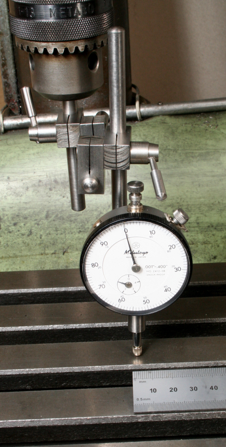
Unfortunately, the above tests do not tell the full story, the reason being they do not take into account the possibility that the workpiece may not be travelling exactly parallel to the table's surface. Sk. 10 shows that even though the spindle is at right angles to the machine table, the workpiece can still approach at an angle if there is an error between the table's surface and the slides on which it moves. Photograph 4 shows the method of testing this requirement with the permitted error levels being the same as those above, that is 0.025mm in 300mm, left to right and back to front. In this case the down feed and the traverse not being used should be locked. Unfortunately, this is a condition that the machine user would find difficult to improve should the error be excessive.
Setting your milling machines tilting head
I have already suggested that shims can be use to set the head of a fixed head machine but the process with a tilting head will be quite different. The problem is that one is trying to set the head within a very narrow band. To quantify this, 0.025 in 300 amounts to a maximum angle of 0.005°
Loosening the head, moving it manually and then re-
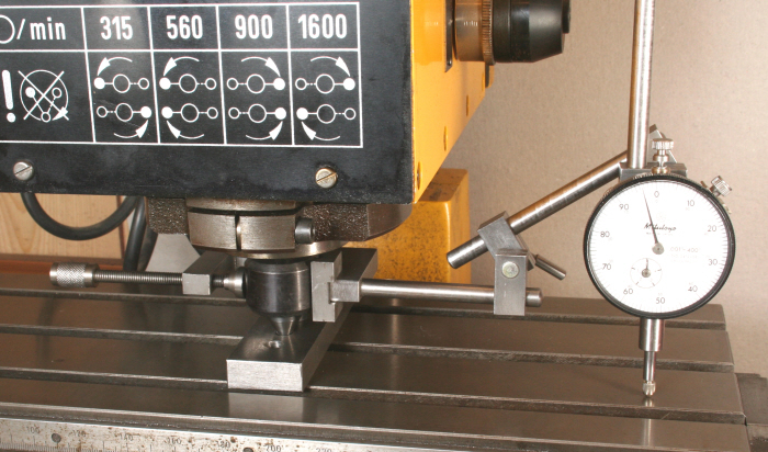
The dial assembly can then be rotated through 180° to establish the error. With the head loosened, the table can now be traversed by a very small amount to rotate the head and the head fixed again in that position then the setting can be checked once more. It is of course, possible to observe the results on the dial whilst the adjustment is being made. Even so, do not expect to arrive at the required setting at the first attempt, or second or third but is should be quicker and easier than the unaided trial and error method.

4

5