
Harold Hall
Workshop Processes


Sketch 3 shows the six common angles that occur on a lathe tool, with Sk.4 showing the common knife tool. However, I will be grinding an alternative to this as shown in Sk.5 which, in use, needs to be set round on the top slide to achieve some of the angles in Sk.4. There is no obvious preferred order for shaping and sharpening the tool but will start by finalising the side clearance, that created by angles 3 and 7.
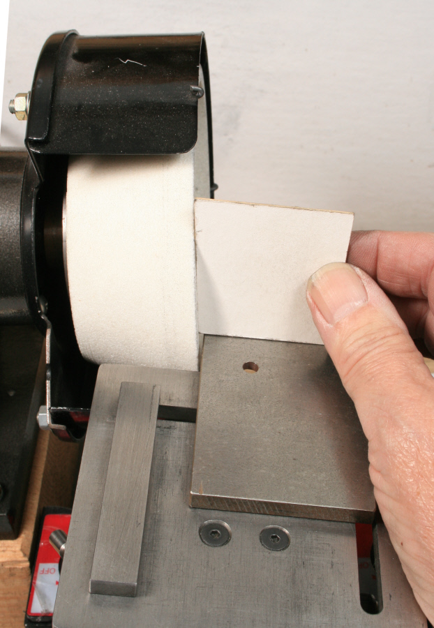
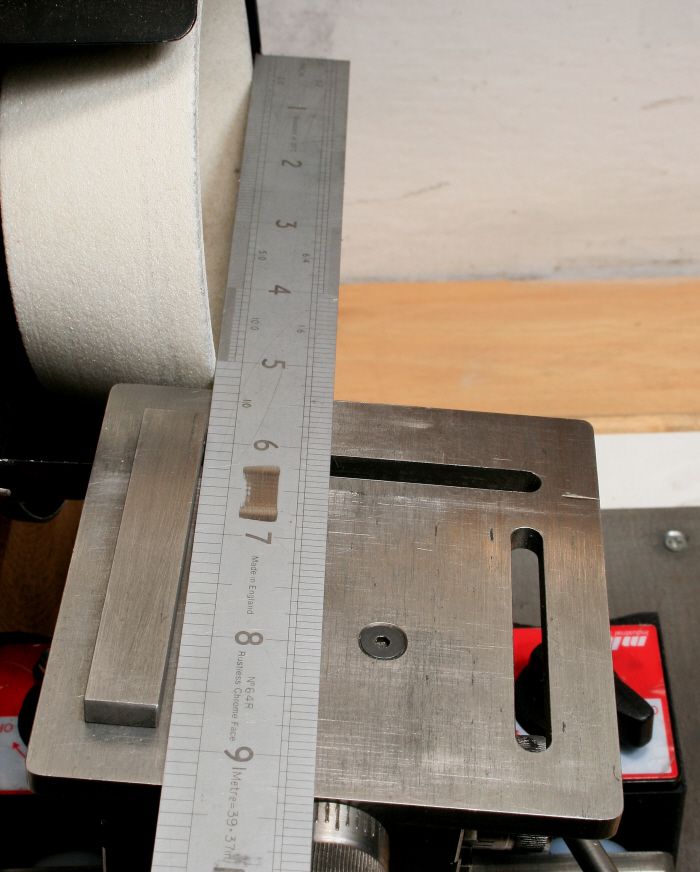
First, the tool holder is set on the swivel base to achieve angle 7, Photograph 3, and the table to the wheel angle set to achieve angle 3, Photograph 4, see also Sk.6. Also, the fence to the wheel face to nominally 2 degrees, Photograph 5. The final table position is then set up using the X (left right) and Y (forward away) traverses.
The Y traverse is used just to bring the table's edge close to the wheel whilst the X traverse is the important one setting the depth being ground away at each pass. This should be no more than 0.02mm when sharpening but can be a little more when finalising the shape initially. Feed the tool manually forward and away, using the fence as a guide, until the number of sparks reduces to just a few, then a further 0.02mm can be applied and the process repeated. Doing this until a satisfactory result is achieve, Photograph 6.
With the one face ground, next angle 1 will be finalised, Photograph 7. The obvious differences are that the table is now tilted much more and down to the left. Also, as there is no top rake ( the slope front to back on the tool), the tool holder has been set in line with the swivel base's edge. Less obvious is the stop screw seen at the end of the fence that ensures the tool will stop at the same position each time and is set using the Y axis traverse. Also less obvious, is that the holder has been moved forward on the swivel base so that the tool reaches the wheel. This necessary due to the swivel base being stopped by the stop screw. The face is then ground using the same method as for the side clearance.


3
4

5


6
7